As I figured, I spent less time on this on the weekend than I had hoped I would. But progress has started to come quickly. I have a ribbon cable and 2x5 pin connector hanging out of my IM-ME like the tongue of a cat. It is connected to four of the five debug points at the back of the unit, while a fifth wire is hanging off 2.5V found off some capacitor in back of the LCD. This connector plugs directly into the Bus Pirate, and I've got a Python script putting the IM-ME into debug mode and reading a few registers. I could post some picture, but the ones at Dave's Hacks are much better than I could be arsed to come up with right now.
That makes it all sound easy, and it should have been. But I made more than my share of stupid mistakes along the way. Like getting the cable on to the back of the IM-ME wrong not once, but twice. And like trying to put the IM-ME into debug mode by strobing the Clock line instead of the Data line. And like thinking I was talking to the IM-ME when really I wasn't getting any further than the Bus Pirate. That's why I don't do this stuff in my real line of work. I'd starve to death if I did.
Next I've got to finish off the routines to re-flash the IM-ME, though I'm most of the way there. Once the building blocks are in place, the IM-ME code will get mass-erased and it will begin its life as the flexible radio receiver this little purple and pink piece of plastic always wanted to be.
But I swear, as I was digging around in its internals last night with a soldering iron and screwdriver, I could swear I heard it sobbing. Ever so softly...
Sunday, January 30, 2011
Saturday, January 29, 2011
Earlier Work Sniffing Vantage Wireless Signals
There is a dearth of information out there on hacking the Davis weather station and I'm not sure why. It is a higher end product that appeals to people who like performance and accuracy in a device. Those same types of people often have a technical background where taking things apart to see how they tick comes naturally. I thought I was the first person who tried to figure out the wireless transmission aspect of these things. It appears that I am actually the second.
Back in 2008, a fellow by the name of Jack Smith at Clifton Laboratories published this post on his blog. He got curious about the wireless transmission from a Weather Envoy remote wireless transceiver. So what did he do? He hauled out his Watkins-Johnson 8617B radio receiver and his Advantech R3463 spectrum analyzer (in both frequency domain and in zero span mode, rather than digging out his Tektronix TDS430 digital scope) and got busy. Now that's what I'm talking about.
His blog post has some really good information that is worth a read, if only to get a good appreciation for how somebody can dig into this stuff with only a few scant bits of information to go on. Unfortunately, it looks like he didn't take his investigation much further than this one post. He also realized that the sun was setting on this data transmission scheme: it ended with the Vantage Pro wireless. He wrote "However, the current production Vantage Pro II uses frequency hopping transmission, which means that you will also have to build a frequency agile receiver and program it to track the hopping transmission". You could, or you could just wait for technology to get to the point where someone comes out with a Pretty Pink Pager that does the hardware design for you.
And speaking of Pretty Pink Pagers, mine is sitting at the Post Office and will be picked up today. Unfortunately I have some other stuff to work on today that will cut into the time I have to play with it this weekend. But I'm crossing my fingers that I can get enough software written this weekend to get my Bus Pirate talking to the IM-ME so that I can at least load Pink OS. Things should get interesting after that, with sniffing some register configurations on the Davis console and hacking some C code to configure the IM-ME in a compatible fashion.
By the way, for whatever reason, Google doesn't give Jack's work the ranking that it should. I had searched around without success for some time to find some information like this. Nothing ever popped up until I came up with some now forgotten magical set of search terms. At least if I blog it here, it will hopefully make this work a little easier to find.
Back in 2008, a fellow by the name of Jack Smith at Clifton Laboratories published this post on his blog. He got curious about the wireless transmission from a Weather Envoy remote wireless transceiver. So what did he do? He hauled out his Watkins-Johnson 8617B radio receiver and his Advantech R3463 spectrum analyzer (in both frequency domain and in zero span mode, rather than digging out his Tektronix TDS430 digital scope) and got busy. Now that's what I'm talking about.
 |
| Weather Station Hacking Equivalent of "First Post" |
And speaking of Pretty Pink Pagers, mine is sitting at the Post Office and will be picked up today. Unfortunately I have some other stuff to work on today that will cut into the time I have to play with it this weekend. But I'm crossing my fingers that I can get enough software written this weekend to get my Bus Pirate talking to the IM-ME so that I can at least load Pink OS. Things should get interesting after that, with sniffing some register configurations on the Davis console and hacking some C code to configure the IM-ME in a compatible fashion.
By the way, for whatever reason, Google doesn't give Jack's work the ranking that it should. I had searched around without success for some time to find some information like this. Nothing ever popped up until I came up with some now forgotten magical set of search terms. At least if I blog it here, it will hopefully make this work a little easier to find.
Sunday, January 23, 2011
Davis Weatherlink Software Not Required!!!!
Better start this post off with an admission. I'm a bonehead. Last night I was sniffing the SPI traffic on my Davis Vantage Pro 2 Wireless weather station console. I was seeing traffic back and forth but couldn't figure out any rhyme or reason behind the data. That is because it isn't there.
The CC1021 chip in this thing talks over two interfaces to the processor. The SPI interface is used to configure the chip, but the data in and out is over a separate digital interface. And that interface doesn't seem to be brought out to the expansion connector at the back of the unit. Oh, bother. So if I want to sniff the data back and forth between the CPU and the wireless chip, I can't do it from the expansion connector. And if it takes hacking the hell out of this thing to get that data, then it isn't something I want to do. So I can spend some time deciphering the register configuration while I wait for my IM-ME to arrive and pick the data up without using the console at all.
But there is more than one way to skin a cat. I had a suspicion that the Weatherlink Module you can buy from Davis for $100 simply passes the commands from the host PC to the processor in the VP2. I mentioned a while back that two serial ports are brought out on the expansion port. Here is a diagram of that port, by the way.

I used my new scope to see if any data was spewing out on either serial port or on PB4, PE2, PE3, or PC4. Nothing. But that didn't mean much. Nothing was asking for data, so nothing was coming out. And this thing tries to conserve power whenever it can. So just for grins, let's open up the VP2 firmware that Davis makes available on their web site in a hex editor.
This is the firmware for the base station. Yet it has the commands that correspond to that of the expansion module that plugs into the back of the VP2 (see this document). It suggests that if I were to hang a serial port off this thing, I might be able to get some data out of it. But not just any serial port will do. The lines on the back of the expansion connector are 0 to 3.3V, whereas a normal serial port might be something like -12V to +12V. And not a lot of PCs have serial ports anymore.
This, of course, is an easy problem to solve, as most people who have played with an Arduino could tell you. I have one of these, strapped to work at 3.3V instead of the +5V it comes configured to by default. If you don't have one already, you can buy this one instead. It is already set up for 3.3V I/O.
Next, I had to wire it up to one of the serial ports exposed on the expansion connector, but which one? Who knows? I guessed and started off with Serial Port 0. Here's the hookup.
WARNING: IF YOU SCREW THIS UP BY WIRING IT WRONG, FORGETTING TO SET 3.3V I/O ON THE FTDI ADAPTER, ZAPPING IT WITH STATIC, OR SOMETHING ELSE BONEHEADED, DON'T COME CRYING TO ME.

So that covers the hardware. Now what about software? All you need is a terminal program. If you are on Windows (sucka!), something like Hyperterm will work. On Linux, I used minicom, crap software that it is. I guessed that the settings I would need would be the same as that they recommend for the Weatherlink adapter: 19.2 kbaud and 8N1. Start googling now if you use minicom, because it is so stinking user unfriendly. Specifically, you'll want to know how to set the port it communicates out of (minicom -s as root, if I remember right). Remember, dmesg is your friend. There are two other things you want to do.
You are now in complete control of this thing.
Try a few other simple commands. VER prints a version date code, NVER is the version string. Again, refer to this document for more coolness. I'm a big fan of STRMON. Just follow it up at some point with STRMOFF or it will print this stuff forever.
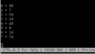
This is the raw data coming from the outdoor unit, and it shows up every two seconds. The "7" on Row 1 is the wind speed in miles per hour (it is hex, so a windspeed of 'a' is 10 mph). Haven't figured out the rest of it yet, but it hardly matters. The serial protocol document linked just above the picture tells you how to get all the processed data out of the thing you could ever want. And today I just tripped over these Perl scripts that should do all the lifting for you. They are written to talk to the Weatherlink dongle, but most if not all of that script should work talking to the unit directly. Come to think of it, there's a lot of weather station software out there written by enthusiasts that should "just work" with this. If you try this out, drop a note in the comments.
So there we have it. No longer do you need to spend $100 on some Weatherlink software that you don't want to get the dongle you do. All you need is a cheap USB to serial converter, and the rest is up to you. I still intend to get wireless reception directly from the remote going once my IM-ME shows up in the mail, but that is probably going to take a little time. Enjoy this for now.
The CC1021 chip in this thing talks over two interfaces to the processor. The SPI interface is used to configure the chip, but the data in and out is over a separate digital interface. And that interface doesn't seem to be brought out to the expansion connector at the back of the unit. Oh, bother. So if I want to sniff the data back and forth between the CPU and the wireless chip, I can't do it from the expansion connector. And if it takes hacking the hell out of this thing to get that data, then it isn't something I want to do. So I can spend some time deciphering the register configuration while I wait for my IM-ME to arrive and pick the data up without using the console at all.
But there is more than one way to skin a cat. I had a suspicion that the Weatherlink Module you can buy from Davis for $100 simply passes the commands from the host PC to the processor in the VP2. I mentioned a while back that two serial ports are brought out on the expansion port. Here is a diagram of that port, by the way.
I used my new scope to see if any data was spewing out on either serial port or on PB4, PE2, PE3, or PC4. Nothing. But that didn't mean much. Nothing was asking for data, so nothing was coming out. And this thing tries to conserve power whenever it can. So just for grins, let's open up the VP2 firmware that Davis makes available on their web site in a hex editor.
 |
| Hmmmm.... |
This, of course, is an easy problem to solve, as most people who have played with an Arduino could tell you. I have one of these, strapped to work at 3.3V instead of the +5V it comes configured to by default. If you don't have one already, you can buy this one instead. It is already set up for 3.3V I/O.
 |
| From the Good Guys at Sparkfun |
Next, I had to wire it up to one of the serial ports exposed on the expansion connector, but which one? Who knows? I guessed and started off with Serial Port 0. Here's the hookup.
WARNING: IF YOU SCREW THIS UP BY WIRING IT WRONG, FORGETTING TO SET 3.3V I/O ON THE FTDI ADAPTER, ZAPPING IT WITH STATIC, OR SOMETHING ELSE BONEHEADED, DON'T COME CRYING TO ME.
So that covers the hardware. Now what about software? All you need is a terminal program. If you are on Windows (sucka!), something like Hyperterm will work. On Linux, I used minicom, crap software that it is. I guessed that the settings I would need would be the same as that they recommend for the Weatherlink adapter: 19.2 kbaud and 8N1. Start googling now if you use minicom, because it is so stinking user unfriendly. Specifically, you'll want to know how to set the port it communicates out of (minicom -s as root, if I remember right). Remember, dmesg is your friend. There are two other things you want to do.
- Turn on your Caps Lock key. Commands to the Weatherlink dongle are all upper case, and it doesn't seem like it wants to make your life easy and convert for you.
- Turn on Local Echo in your terminal program, or whatever option it is that echos back the characters that you type. The Weatherlink dongle doesn't do this, so you'll be typing blind otherwise.
You are now in complete control of this thing.
Try a few other simple commands. VER prints a version date code, NVER is the version string. Again, refer to this document for more coolness. I'm a big fan of STRMON. Just follow it up at some point with STRMOFF or it will print this stuff forever.
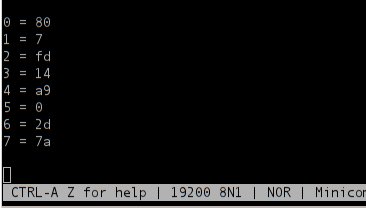
This is the raw data coming from the outdoor unit, and it shows up every two seconds. The "7" on Row 1 is the wind speed in miles per hour (it is hex, so a windspeed of 'a' is 10 mph). Haven't figured out the rest of it yet, but it hardly matters. The serial protocol document linked just above the picture tells you how to get all the processed data out of the thing you could ever want. And today I just tripped over these Perl scripts that should do all the lifting for you. They are written to talk to the Weatherlink dongle, but most if not all of that script should work talking to the unit directly. Come to think of it, there's a lot of weather station software out there written by enthusiasts that should "just work" with this. If you try this out, drop a note in the comments.
So there we have it. No longer do you need to spend $100 on some Weatherlink software that you don't want to get the dongle you do. All you need is a cheap USB to serial converter, and the rest is up to you. I still intend to get wireless reception directly from the remote going once my IM-ME shows up in the mail, but that is probably going to take a little time. Enjoy this for now.
Saturday, January 22, 2011
Davis SPI Traffic
I've been a bit quiet lately thanks to some work-related travel and some lack of hardware. But the traveling is done for the time being and some of the much-awaited hardware has arrived. It is time to get back to hacking my Davis VP2 Weather Station.
This is a measurement of the SPI traffic, courtesy of my new Rigol 1052E scope (and no, I have not hacked it yet, but I fully intend to). Yellow is MISO data and blue is SCK. This shows that the I2C clock is a pretty manageable 920 kHz, which just happens to be half the CPU frequency. Second, measurements on a wider timescale shows very little traffic. This is to be expected: the outdoor unit is essentially solar powered and you want to conserve that power as much as possible.
The next thing to do is hook up my newly arrived Bus Pirate and see if I can make sense of the data going back and forth. Cool.
This is a measurement of the SPI traffic, courtesy of my new Rigol 1052E scope (and no, I have not hacked it yet, but I fully intend to). Yellow is MISO data and blue is SCK. This shows that the I2C clock is a pretty manageable 920 kHz, which just happens to be half the CPU frequency. Second, measurements on a wider timescale shows very little traffic. This is to be expected: the outdoor unit is essentially solar powered and you want to conserve that power as much as possible.
 |
| The SPI Equivalent of "First Post" |
Sunday, January 16, 2011

Sunday, January 9, 2011
Bus Ninja!
Why have I not heard of this before? Bus Ninja is a clone of the Bus Pirate that runs on Arduino and Teensy! If this works, it should let me snoop on the SPI traffic on my Davis VP2 console while I wait for my Bus Pirate to arrive.
After letting the author know that the download link to his software wasn't working, I dove in. The homepage for this project lets you know that there is some makefile tweaking involved. First thing I had to sort out was that I have a Boarduino equipped with an Atmega 328P and not an Arduino with an Atmega 168. The file config-arduino.mk has a line with
but I figured that would just affect the compilation and I'd be OK to leave this as is. The difference between the two is just memory size: the pinouts are the same. So then I did
which went fine, but
died with
Hmmmm. Looks like the version of avr-gcc in arch linux doesn't have this parameter so I had to comment that CFLAG out of Makefile. Everything compiled nicely after that.
Next, I didn't want to load up the Arduino IDE, preferring instead to program the chip from the command line. I have a Sparkfun FTDI breakout board, so I needed to get Linux talking to this thing. Let's plug it in and see if Linux sees it?
So far, so good. But I went down many blind alleys after this. First, because I am using this FTDI serial converter, I thought I needed to install the Arch Linux libftdi package. Turns out I don't. Second, a lot of stuff I read seemed to indicate that if I wanted to do this from the command line, I needed a patched version of avrdude (see here). Turns out I don't. Basically, with the Sparkfun FTDI board, you can tell avrdude that you are using the stk500v1 programmer. But, the Sparkfun board adds some special sauce: it brings out DTR on Pin 6 of the header to reset the board. We need to tell this to avrdude. So the config file for the stk500v1 programmer ends up looking like this in /etc/avrdude.conf (note the last line)
Now let's see if this works. As root, do
This harmless command tells avrdude to read the setting of the hfuse on the micro. Note some very important things here:
I've taken the spaces out between the command line arguments as avrdude doesn't seem to care either way. Now, all it takes as root is
to load the Bus Ninja code into the Arduino. YES! Stay tuned for next time when I'll try messing with the Bus Ninja program itself.
After letting the author know that the download link to his software wasn't working, I dove in. The homepage for this project lets you know that there is some makefile tweaking involved. First thing I had to sort out was that I have a Boarduino equipped with an Atmega 328P and not an Arduino with an Atmega 168. The file config-arduino.mk has a line with
MCU=atmega168but I figured that would just affect the compilation and I'd be OK to leave this as is. The difference between the two is just memory size: the pinouts are the same. So then I did
make BOARD=ARDUINO cleanwhich went fine, but
make BOARD=ARDUINOdied with
cc1: error: invalid parameter 'inline-call-cost'Hmmmm. Looks like the version of avr-gcc in arch linux doesn't have this parameter so I had to comment that CFLAG out of Makefile. Everything compiled nicely after that.
Next, I didn't want to load up the Arduino IDE, preferring instead to program the chip from the command line. I have a Sparkfun FTDI breakout board, so I needed to get Linux talking to this thing. Let's plug it in and see if Linux sees it?
# dmesg

usb 3-1: new full speed USB device using uhci_hcd and address 2

usbcore: registered new interface driver usbserial

USB Serial support registered for generic

usbcore: registered new interface driver usbserial_generic

usbserial: USB Serial Driver core

USB Serial support registered for FTDI USB Serial Device

ftdi_sio 3-1:1.0: FTDI USB Serial Device converter detected

usb 3-1: Detected FT232RL

usb 3-1: Number of endpoints 2

usb 3-1: Endpoint 1 MaxPacketSize 64

usb 3-1: Endpoint 2 MaxPacketSize 64

usb 3-1: Setting MaxPacketSize 64

usb 3-1: FTDI USB Serial Device converter now attached to ttyUSB0

usbcore: registered new interface driver ftdi_sio

ftdi_sio: v1.6.0:USB FTDI Serial Converters Driver
So far, so good. But I went down many blind alleys after this. First, because I am using this FTDI serial converter, I thought I needed to install the Arch Linux libftdi package. Turns out I don't. Second, a lot of stuff I read seemed to indicate that if I wanted to do this from the command line, I needed a patched version of avrdude (see here). Turns out I don't. Basically, with the Sparkfun FTDI board, you can tell avrdude that you are using the stk500v1 programmer. But, the Sparkfun board adds some special sauce: it brings out DTR on Pin 6 of the header to reset the board. We need to tell this to avrdude. So the config file for the stk500v1 programmer ends up looking like this in /etc/avrdude.conf (note the last line)
programmer id = "stk500v1"; desc = "Atmel STK500 Version 1.x firmware";
type = stk500;
reset = 6;Now let's see if this works. As root, do
# avrdude -C /etc/avrdude.conf -c stk500v1 -p m328p -P /dev/ttyUSB0 -U hfuse:r:-:h -b 57600This harmless command tells avrdude to read the setting of the hfuse on the micro. Note some very important things here:
- I am using -p m328p here because my Boarduino has an Atmega 328P rather than the 168 in many Arduinos.
- I am using -P /dev/ttyUSB0 because that is what dmesg told me was being used.
- I am using -b 57600 to lower the baud rate from the default. I WASTED SEVERAL FRUSTRATING HOURS ON THIS. Go too fast and avrdude comes back with the very unhelpful 'avrdude: stk500_recv(): programmer is not responding'. Your mileage wil vary depending on the speed of your processor. If you get this dreaded message, try slowing things down even further.
PROGRAM_CMD=avrdude -C /etc/avrdude.conf -pm328p -cstk500v1 -P/dev/ttyUSB0 -b57600 -D -Uflash:w:$(TARGET).hexI've taken the spaces out between the command line arguments as avrdude doesn't seem to care either way. Now, all it takes as root is
# make BOARD=ARDUINO programto load the Bus Ninja code into the Arduino. YES! Stay tuned for next time when I'll try messing with the Bus Ninja program itself.
Friday, January 7, 2011
An alternative Davis VP2 Console???
It's so crazy, it just might work.
I was mindless surfing the Makezine blog when I came across a list of their top ten hacks for 2010. Somewhere in the middle was a $16 spectrum analyzer. Cool. I start reading it over and notice that this baby is based on a Texas Instruments CC1110f32 chip. Upon first read, this appeared to bear some similarities to the CC1021 in the VP2 console. The CC1110 is actually a CC1101 with an embedded 8051 microcontroller on chip. The next question then becomes, is the CC1101 compatible with the CC1021. Well yes, yes it is. So in theory, you could use this cheap pink instant messaging terminal as a Davis Wireless Weather Station receiver, with an included USB receiver to facilitate connection to a PC.
How awesome would this be???
 |
| Love The Color |
How awesome would this be???
Monday, January 3, 2011
A Davis VP2 Update
I took apart my Davis VP2 wireless weather station console again today over the protests of my lovely wife. It was a pretty productive exercise and I learned several things.
First, I've traced out the connections between the front panel buttons and the processor. The sixteen keys are wired in a 4 row x 4 column matrix (shocking, I know). The eight lines are connected to PC0-PC3 and PE4-PE7 on the processor. Still to do is figure out is which pins are configured as outputs and which as inputs.
That might not be so important now that I've also figured out the wiring to the expansion connector on the back of the unit. Here's how it breaks down:
So I have a number of things on my TODO list.
First, I've traced out the connections between the front panel buttons and the processor. The sixteen keys are wired in a 4 row x 4 column matrix (shocking, I know). The eight lines are connected to PC0-PC3 and PE4-PE7 on the processor. Still to do is figure out is which pins are configured as outputs and which as inputs.
That might not be so important now that I've also figured out the wiring to the expansion connector on the back of the unit. Here's how it breaks down:
- Four pins are connected to the SPI port on the Atmega 128: SS*, SCK, MOSI, and MISO.
- Two pins are connected to TXD0, RXD0. Another two pins are connected to TXD1, RXD1.
- There are a couple seemingly miscellaneous connections to PB4, PC4, PE2, and PE3. Not sure what these would do. Might the processor use these to sense the presence of the expansion module?
- There are two connections to VCC, two to GND, and one to the wall-wart DC IN via a diode.
- There is a connection to RESET*
- There are two pins that are not connected.
So I have a number of things on my TODO list.
- Figure out how to use EAGLE and make a schematic of the circuit as I understand it so far.
- See if I can figure out how the various ports are programmed on the Atmega. I should be able to use simavr for this. Some playing around earlier this week showed me how to load a piece of firmware into a simulated Atmega and have it run in single step mode.
- See if I can snoop the SPI traffic. That will likely have to wait until my Bus Pirate shows up. Learning how SPI works in the first place wouldn't hurt.
Subscribe to:
Posts (Atom)